Internal gate cutting is always designed for edge gate cutting.
When working with a cut gate, it is difficult to ensure that the size and depth of the scars at the cuts of each product are consistent due to the different skill levels of the workers and the uneased size of each force.
Internal gate cut occurs at the time before the start of the cooling after the end of holding pressure, cutter cut off the gate, so that the gate and the product in the mold are disconnected, this can save the manual cost of the products, reduce some artificial quality problems, shorten the production cycle, improve the stability of production.
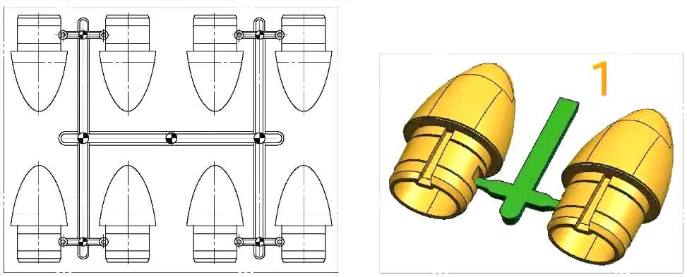
As shown in Figure 1, the edge gate's J-gate is a way of manufacturing common products, using J- gate to do the injection, after ejection, and then artificial cut gate, the following mold is to be made into internal gate cut.

1. Cutter's design
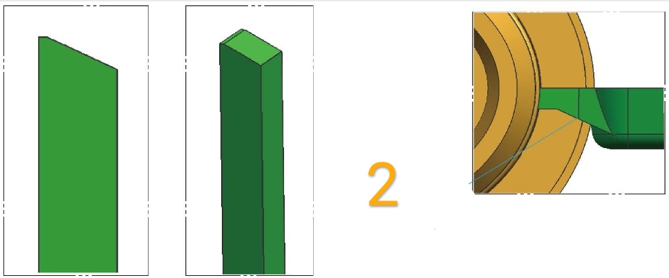
Common cutter directly uses the flat ejector pin, according to the difference of the gate, making the top surface into the required shape, in order to cut off the gate, the top surface of the cutter shape as shown in Figure 2.
Notice:
The top surface of the cutter is sloped because the bottom of the product gate has tapered.

2. Mold structure
The mold structure, as shown in Figure 3, is under the ejector plate, add a piece of ejector plate to it, the bottom ejector plate, which fixes the cutter on the bottom ejector plate, and the movement of the bottom ejector plate is controlled separately by hydraulic.
When holding pressure is completed, the hydraulic pull the ejector plate forward, cutter automatically cuts off the gate.

Design specifications:
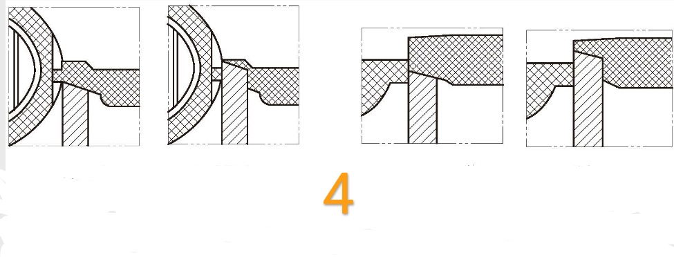
1. Due to the short stroke of the cutter movement, please note the limited distance of the bottom ejector plate and don't let the cutter collide with the cavity. Normally, there should be at least a 0.5mm gap between the cutter top surface and the cavity after the gate is cut off, as shown in Figure 4.

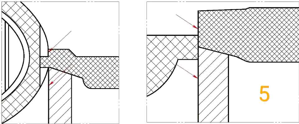
2. Different parting of the product results in different designs at the lancing, as shown on the left side of Figure 5 when the product is parted from the middle, the filling has a section of de-filling, cutter and the product set aside a position, the highest point of this position should be lower than the product's un-reduction surface, to ensure that the gate residue does not affect assembly.
3. On the right side of Figure 5, the product is a plane parting and the cutter side can be designed next to the side of the product to ensure that the gate cut-off surface is neat and flat.

4. There should be a 0.02mm gap between the cutter side and the cavity side to prevent two sides from colliding, as shown at the arrow in Figure 5.
5. In addition to the cutter, all other ejector pins are placed on the upper ejector plate, after opening the mold, the ejector plate will be ejected by the knockout.


