The structure shown in figure 1 is based on the ejector plate to achieve double ejection.

Among of numbers:
Number 1 stands for draw hook
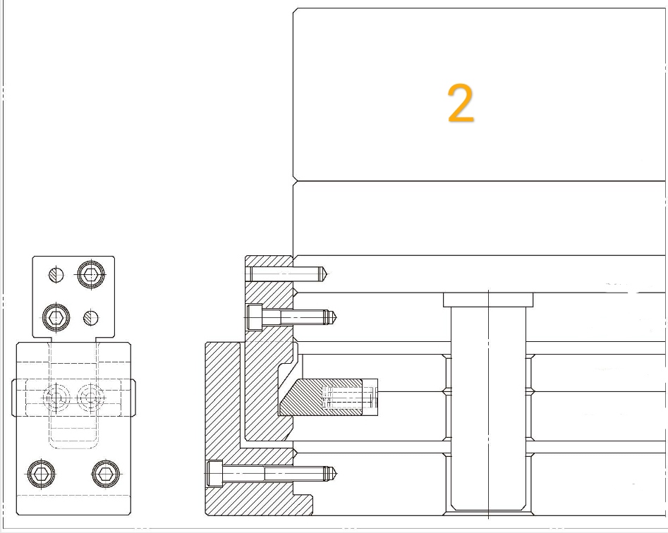
Number 2 stands for pull block
Number 3 stands for lever pin
Letter S stands for the stroke
As shown in figure 2, the draw hook is installed on the upper group ejector plate, the lever pin is put on the lower group ejector plate, and the pull block is fixed on the bottom plate, which can only be installed on the outside of the mold.

The process of the movement is displayed in below picture,


