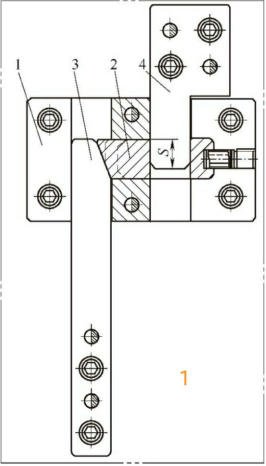
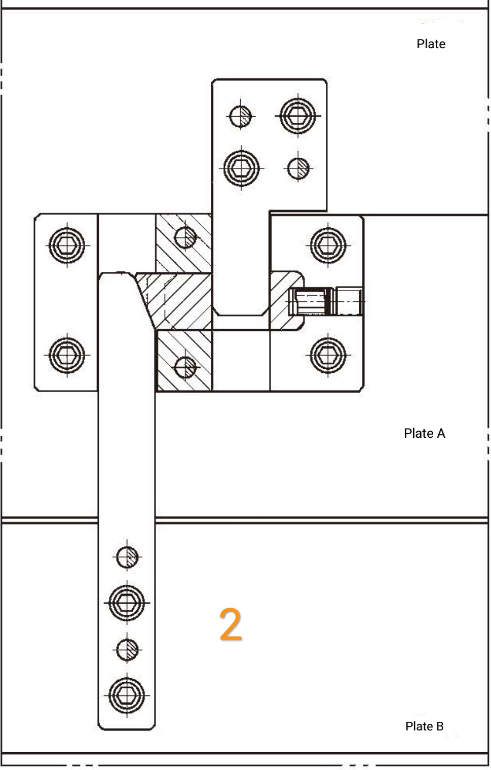
Figure 1 shows the controlling process when we clamp a mold, and figure 2 shows our real application case.

In figure 1, number 1 means the fixing pedestal.
number 2 means a lever pin.
number 3 means machining shovel.
number 4 means stripper bar.
number 5 means stroke.
When we clamp the mold following the designation, we have to close plate A and plate B, before clamping the plate and plate A, see figure 2 below.

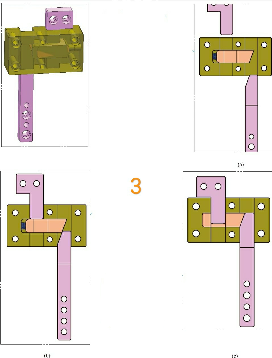
The principle of clamping a new mold is expressed in the below pictures.

In the open mode state displayed by (a), both the top block and the machining shovel. have been removed from the fixed seat, waiting for the mold closing job.
From the (b), notice, during mold clamping, the stripper bar remains open against the lever pin as long as the template where the machining shovel and the fixing pedestal are located are not moved to the correct position.
From the (c), the template where the shovel base is located and the template in which the fixing pedestal is located are moved to the correct position, and the shovel makes the lever pin return to its original position, leaving space for activity, the stripper bar is detached from the lever pin, and the mold continues to fit smoothly.
Our designation specifications and how we choose proper elastic parts when there's a risk during the process of mold clamping.
1. Because the stripper bar and the lever pin have a larger force in the mold clamping process, with the reduction of contact area, the force area will become smaller and smaller, resulting in premature wear and tear of the corners, and even damage. Therefore, the angle must be R angle, but should not be too large, otherwise affect the molding process.
2. Due to the gap and the corner R of the stripper bar, the structure can not be 100% accurate in the stroking process, it is possible that the stripper bar will squeeze the lever pin back when a small part of the mold clamping is not fully fit. Therefore, when there is a risk of collision, it is forbidden to use this structure alone, it may be considered to add spring glue or to assist with nitrogen springs.
3. This structure can be used alone in some cases when this structure gap and movement trajectory are not sufficient to affect the mold structure, but it is recommended to add spring glue or spring to reduce risk.
4. To prevent premature wear, the lever pin should use quenching materials, while other parts can be nitrided using P20 materials.
5. The machining shovel, the stripper bar, and the fixing pedestal should all be positioned well.


