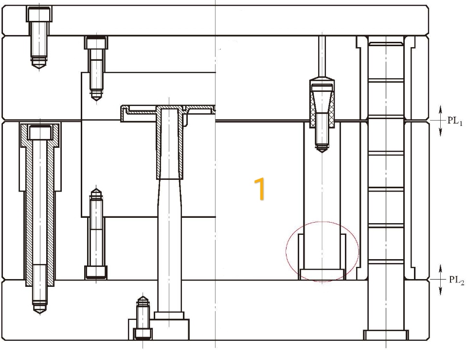
The structure of time-lapse core pulling by cavity movement is based on the time-lapse of synchronous core-pulling by cavity movement structure to prevent the sticking cavity and other risks after products core-pulling, the sequence of the opening mold is completely different.
To achieve the time-lapse function, we always do a group of an active pin, lock the parting lock on the active pin, and design the relief part on the active pin's sinking platform, the relief part for the sinking platform's upper surface is decided by time-lapse, as marked by the red circle in figure 1.

Design specifications:
1. Need to do stop block between the stripper plate and plate B, the stop stroke is equal to the distance of priority core-pulling.
2. Stripper plate opening the mold is pulled by plate A, as the parting lock is locked on the active pin, the stripper plate won't move before the active pin's sinking platform touches the stripper plate. Once the stripper plate is moved by other components, we always put a casting polyurethane between plate A and the stripper plate.
3. The sequence of opening a mold is to open a part of PL1 first until the product disconnect the cavity, then open PL2, when the PL2 is opened to a preset distance, the parting lock leaves the cavity and continues to open until the end.
4. Do not put a spring between the stripper plate and plate B because of the sequence of opening mold.
5. Put a block at the return pin if the ejector plate needs to move along with the stripper plate synchronously, if no need, design the return pin as standard mold.
6. The force point of the spring at the ejector plate should be acting on the stripper plate through plate B, otherwise, the spring and the parting lock will be counterproductive. When the parting lock is detached, the spring pulls back the stripper plate, which can be added if the spring length is not enough.
