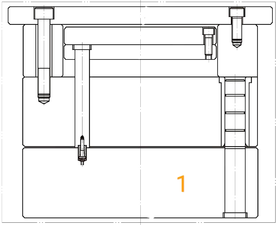
The most common use of parting lock ejection is when the cavity needs to be ejected (e.g. when the cavity has a lifter or partial ejected), as shown in figure 1, the general method is to put a resin party lock on the return pin of the cavity, using the power of the mold opening to pull the cavity's ejector plate to eject.

Design specifications:
1. To simplify the mold, the parting lock is mostly installed directly on the return pin. Since the return pin should be pressed against the return pin when the ejector plate is back in position, the return pin should be larger in diameter than the parting lock to ensure that the return pin has enough surfaces to be pressed. Since there is an R angle at the lip of the parting lock hole, as shown in figure 2, it is necessary to ensure that the A size in the figure is more than 1.5mm.
2. To ensure force balance, the installation position of the parting lock should be symmetrical. Normally, a parting lock should be installed on each return pin, or one on the verse return pin if the ejection area is small and less stressed.
3. In order to ensure the service life of the parting lock, the edge of the parting lock should be inverted R angle, the general R angle value range from 1.5mm to 2mm, return pin should be done on the sinking platform.
4. When the mold is closed, plate B resists the parting lock first, forcing the cavity ejector plate to return first. If there is a risk such as clashed dies in the mold structure, suggest to use other structures (e.g. spring ejection) or take appropriate precautions.
5. When locking a parting lock, to prevent the return pin from turning, the return pin's countersink should do the location.


